This tutorial shows you how to create a circular crosshair using a widget blueprint with a material. As always, there are many methods available but this one has some key advantages:
- Material parameters let you modify the crosshair in realtime. In this tutorial we will use a material parameter to optionally fill the circle.
- No texture manipulation needed with external software.
- The colour of the crosshair can be easily changed, both in the editor and during runtime.
This is what the final crosshair will look like. I’ve wired up the “F” key to fill the crosshair for demonstration purposes, but my game will ultimately fill the inside when the player is aiming at an interactable object.

The basic outline of what we’ll be doing is as follows:
- Create a material with two radial gradients, one for the outline and another for the inner circle.
- Create a Widget Blueprint with an image component.
- Apply the material to the image.
- Draw the widget in the viewport.
- Set up an event handler to change the “FillCrosshair” parameter on the material.
I’ll first show you how to create the outer circle in case that’s all you need.
Creating the outer circle
What we’ll be doing here is creating is two circular gradients; a smaller one subtracted from a bigger one. What you’ll end up with is what appears to be just the outline of a circle.
Fire up your project or whatever template you’d like to use. I’ll be using the FPS template with some basic blocked out level stuff and the gun and arms removed.
Create a new material. I called mine M_Crosshair. Double-click it.
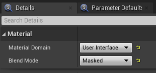
In the Details panel, under Material, set Material Domain to User Interface and Blend Mode to Masked.
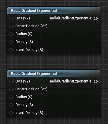
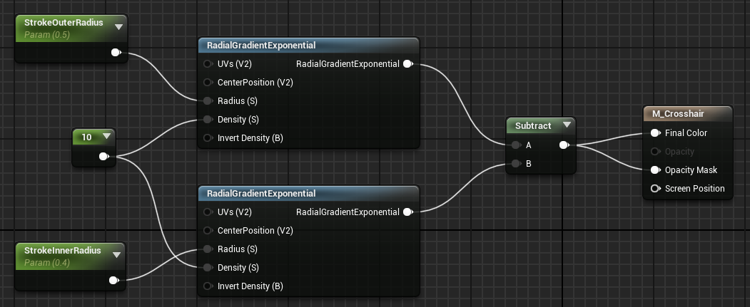
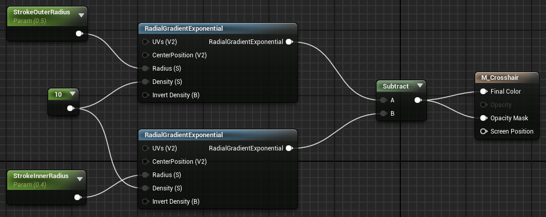
Add two RadialGradientExponential nodes. One will draw the aforementioned bigger circle, and the other the smaller.
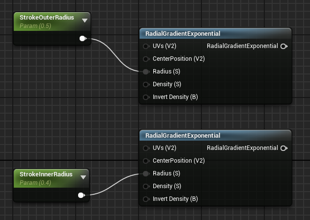
To set the radius of each one, add two ScalarParameter nodes to the left of the RadialGradientExponential nodes. Name the top one StrokeOuterRadius (I’m using “stroke” as that’s typical for graphics apps) and the bottom one StrokeInnerRadius.
Set the default value of StrokeOuterRadius to 0.5 and StrokeInnerRadius to 0.4. Plug StrokeOuterRadius’s output pin into the top radial gradent’s Radius (S) pin. Likewise for StrokeInnerRadius and the other radial gradient.
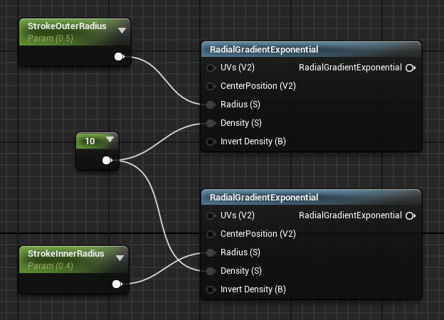
Create a Constant node (protip: hold the “1” key and left-click on the canvas), set its value to 10, and plug that into the Density (S) pin of both gradients.
At this point, if you preview either of the gradient nodes (right-click -> Start Previewing Node) you will see that each draws a circle. One smaller than the other. Just as I promised.
To get the final outline, we need to subtract one from the other. Add a Subtract node to the right of the existing nodes. Plug the top gradient (the bigger circle) into A and the other into B. Plug the output of the Subtract node into both the Final Color and Opacity Mask pins of the material output node.
That’s it for the material creation.
Back in the asset browser, create a Widget Blueprint (right-click -> User Interface). I called mine WBP_PlayerHUD. Open that sucker up.
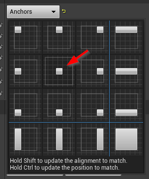
Drag an Image from the Common section of the Palette onto the canvas. In the Details panel, set its anchor to the centred one.
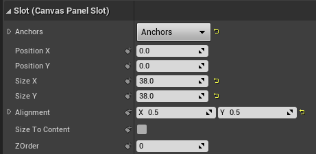
Set the Size X and Size Y to whatever you like. Somewhere between 20 to 40 will probably be about right. Set Alignment X and Y both to 0.5, which ensures the image is properly centred.
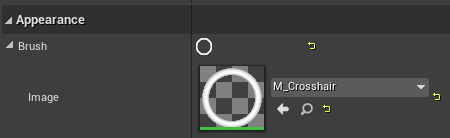
Under Appearance, select your material in the Image dropdown.
You can use the Tint field under Appearance if you want to tinker with the colour.
That’s it for the canvas. You’ll notice that we used ScalarParameters for the Radius inputs for the gradients. This is so that you can change them at runtime. You could have also used Constant nodes instead if you’re not interested in changing them at runtime.
If all you want is just the outline of the crosshair, then you can stop here or skip to the section where we add it to the viewport.
Creating the circle fill
If you want a filled circle, you could just keep one of the gradient nodes from the first section. That’s not quite what I needed, though. I wanted to have the inside filled, but with a small gap between the filling and the crust, err… outline. I also wanted to be able to toggle this fill on or off, so we’re going to leave the outline as is and create another circle to place inside it.
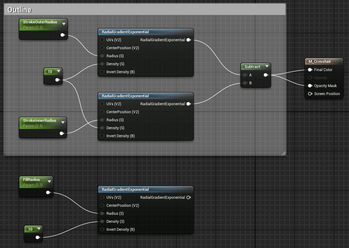
Open up your crosshair material again. It should look like this at the moment:
Duplicate the Constant (the “10” node), one of the ScalarParameters, and one of the gradients. Place them below the other nodes. Rename the ScalarParameter you copied to something like FillRadius, and set its Default Value to 0.3. Astute readers may have noticed that 0.3 is slightly smaller than the inner radius of the outline, leaving us a gap of 0.1. Your nodes should look like this (I’ve wrapped a comment around the outline’s nodes to help visually separate it):
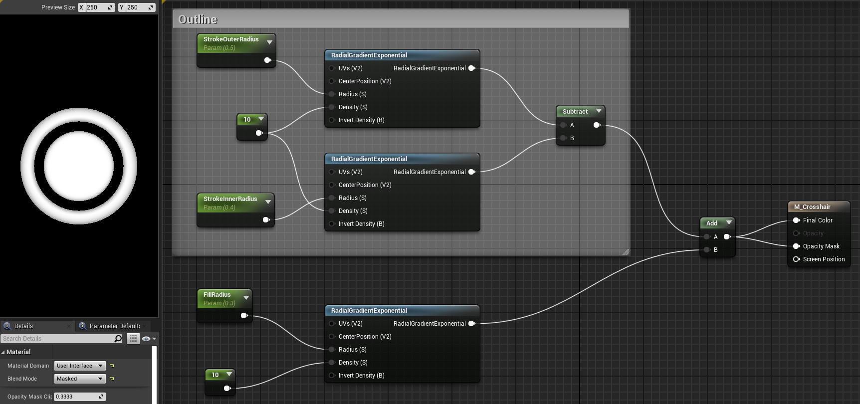
If you add the outline circle (the output of the Subtract node from earlier) to the fill circle by using an Add node, you’ll end up with the filled circle.
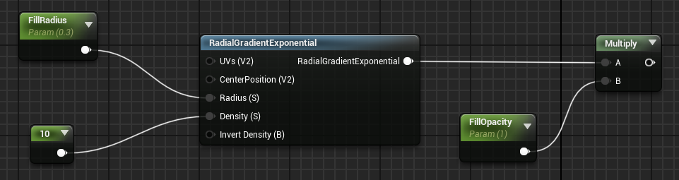
That’s great, but how do we make it optional so that we can disable the fill at runtime? You can’t do boolean parameters as such in shaders, so we’re going to use a little trick; we’re going to use another ScalarParameter ranging from 0 to 1 and multiply the output of the fill circle’s gradient by it to hide or show the circle respectively.
Add a Multiply node to the right of the fill circle’s gradient. Plug the output of the gradient into the A pin. Add a ScalarParameter, call it something like FillOpacity, set its Default Value to 1.0 (or 0.0 if you want to start with it hidden), and plug it into the B pin of the Multiply node. The fill circle section should now look like this:
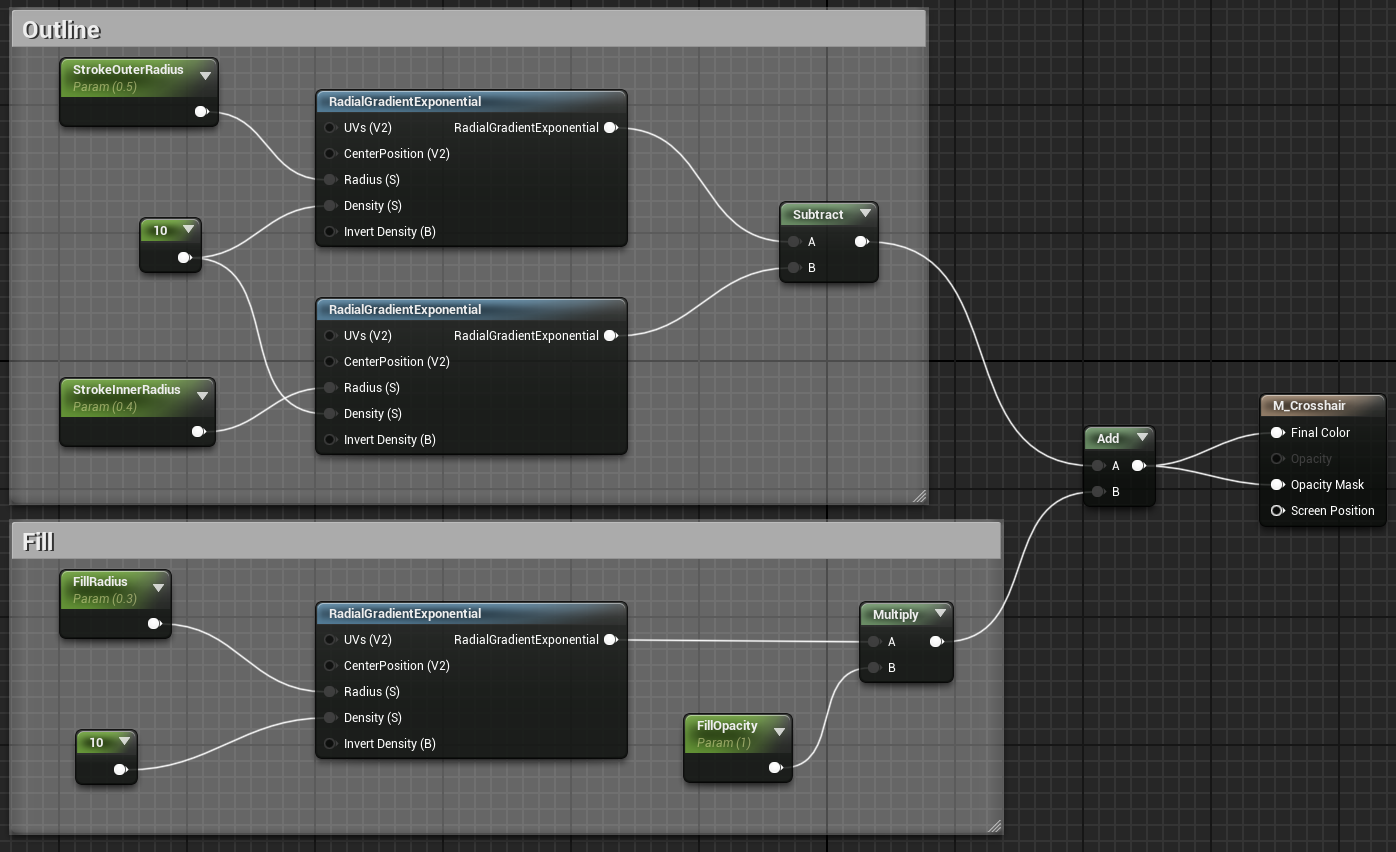
Finally, plug the output of the Multiply node into the B pin of the Add node from earlier. Now you should have a crosshair whose inner circle can be shown or hidden based on the value of the FillOpacity parameter. The final material looks like this (with another comment added):
Adding the crosshair to the viewport
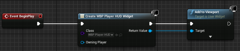
This part is easy peasy. Open up your character Blueprint and make sure you have an Event BeginPlay node. Add a Create Widget node and choose your Widget Blueprint from earlier in the dropdown under Class. Add an Add to Viewport node next to that one and plug the return value from the Create Widget node into the Target of this one. You should end up with the following:
That’s it! Your Widget Blueprint will now be drawn to the screen when you begin playing.
Modifying materials at runtime
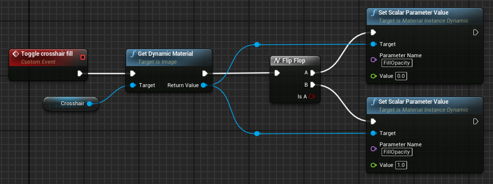
This part is also really easy. In your Widget Blueprint, right-click the canvas and create a Custom Event. I called mine “Toggle crosshair fill“. Add a Get Dynamic Material node next to that, and drag the Crosshair image (it might be called Image0 if you didn’t rename it) onto its Target pin. Create two Set Scalar Parameter Value nodes to the right of the other pins. Type the name of the last parameter we added to the material (FillOpacity) into the Parameter Name field of both nodes, and a value of 0.0 in one and 1.0 in the other. Chuck a FlipFlop node between these and the Get Dynamic Material node and you’ve got yourself a toggle event you can call from anywhere you like. The final setup looks like this:
I hope this helps someone. I’m not an expert in Unreal Engine but this seems a reasonable approach to solving this particular problem. If you have any suggestions for improvement, please let me know.
Nice tutorial, very easy to follow!
I have two problems though, in 5.0.3 the Set Scalar Parameter Value node doesn’t have a input value, so no where to set it at 0 and 1.
My crosshair is also visible as a square out in the corner of my view and not center. What can be the reason for it?
Thanks!
Thanks for your comment, I’ll try this in 5.x when I get a chance and get back to you.
I have been able to follow this tutorial in last UE5 version as for today with no issues. Thanks!
Thanks! It was very helpful!